
There are two control mechanisms in a wind turbine: the torque control and the blade pitch control.
The purpose of blade pitch control
There are two control mechanisms in a wind turbine: the torque control and the blade pitch control.
- The torque control regulates the generator torque to keep the power constant at low wind speed (below rated wind speed).
- The blade pitch control pitches the blades to keep the rotor speed constant at high wind speeds (above rated wind speed)
At wind speeds above rated, the blade pitch controller pitches the blades out of the wind to reduce aerodynamic lift. An effect of pitching the blades is also that the thrust force on the rotor is reduced. For a floating wind turbine the motion of the floater can be considerable, causing the rotor to experience an "apparent wind speed". When the floater pitches forward, the apparent wind speed increases. Consequently, the controller pitches the blades to maintain the rotor speed, and the rotor experiences a reduction in thrust force. The opposite happens when the turbine pitches backwards.
Negative aerodynamic damping
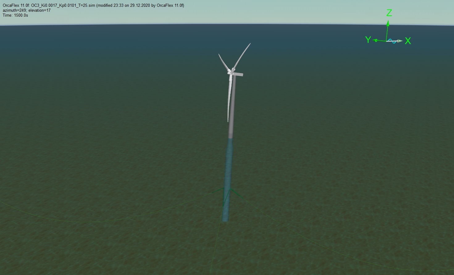
The positive feedback to the floater pitch motion described above is often referred to as negative damping. Negative damping must be mitigated, as it dramatically reduces the fatigue lifetime of the structure.One solution is to make the blade pitch control slower than the floater pitch motion, i.e. keep the natural period of the blade pitch control well above the floater pitch natural period. The blade pitch controller is a PI-controller, and the magnitude of the P and I gains determines the natural period and damping of the controller. We illustrate the impact of the controller gains by playing with the NREL 5MW reference wind turbine controller. The floater is a spar-buoy type similar to the Hywind demo floater and is also used for the OC3. This study is conducted in Orcaflex and is a coupled aero-hydro-servo-elastic simulation. See this page for example of CFD on the same floater.
Impact of pitch control period on floater motion
The video shows a comparison of fast onshore controller (left) and slow controller suited for floating turbine (right). Wave height is 6m and period is 15s for both cases.
The plot below shows a comparison of turbine pitch motion for different blade pitch controller natural frequency/response time. The wind speed is 15 m/s, just above rated speed (11.4m/s), and the controller response time is reported in terms of percent of turbine pitch natural frequency.
- The blue curve shows response using typical onshore gains with almost twice the frequency of the pitch natural frequency.
- The yellow is for gains with its natural frequency of 85% of turbine pitch natural frequency. For the NREL 5MW this is a period of about 30 s.
- The orange shows typical floating turbine gains with controller period of about 50s.
- The grey curve is for a turbine in parked condition, without controller and the blades are pitched at 90 deg.


